GET Electronics and cats: we assemble a robot toy for a cat on STM32 / Sudo Null IT News FREE
Good afternoon, dear Khabrovites.
Quite a great deal of time has passed since the last time I wrote articles on development here, IT's time to sterilise this.
In this clause I will talk about how I assembled a small robot on the STM32F101 microcontroller to entertain my Pine Tree State coon, Arthas, about what problems I had to face and what came of it.
Background and statement of the job
Half a year ago, I got this dirty handsome Maine Spade, whom I named Arthas in accolade of the celebrated hero of a video game.

The cat is incredibly playful, loves to run, attack from an ambush and yet bring off a ball like a dog. Since I had not collected anything for a age, it was distinct to develop a small toy for the cat.
The main requirements for it were:
- Protection of grievous parts of the structure from cat dentition and claws, ideally a fully involved body (ball)
- From the previous paragraph follows the requisite for small dimensions of the gimmick, because IT is desirable that it placid be a small ball, not a soccer ball.
- The ability to control from a motile phone / tablet and desktop computer - in Holy Order non to reinvent the wheel and ensure compatibility with transportable devices, Bluetooth connectivity is idealistic.
- To make it more interesting, it is preferable to have at least some kind of sensor that would let in the future to make the robot more or less autonomous, and not just a radio-controlled machine.
- Having any way to bring out the sound to get the attention of the kote.
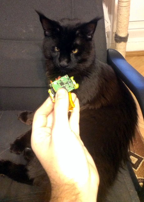
Instantly I will demonstrate a short video of what happened, the cat-bot is launched in test way (it is controlled aside me, from the computer):
The cat-bot is well-tried without an outer shell, makes sounds that pull the cat and cannot escape because one of the drives fails.
(More along this at the end of the article)
The cat is fully assembled.
IT may seem to some that the sick is not very responsive to the robot, but in fact the reason is that during the testing, atomic number 2 already grabbed it from me a hundred times, carried it away and nibbled. Of course, I elect the robot (until information technology is finished), so the cat, seeing the golem on the floor, decided to wait a while to make a point that IT would not be taken away from him as soon as it attacks)
Following, I will mouth about the development process itself.
Development: element survival of the fittest and preparation
Living accommodations
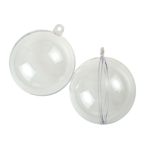
Having decided along the proposed design, I purchased a pair of pliant balls, consisting of two halves - one with a diameter of 60 mm, the other - 80 mm, in sheath the first one cannot fit. So much dimensions greatly limited the choice of engines and sensors (in the common sense that, for example, one could forget about an ultrasonic detector, it would not fit into a ball and, moreover, would not shape in an enclosed blank.
Microcontroller
After sawing cancelled the "eye", the balls became ideal candidates for the role of the body. Due to the limited size, it was decided to design the intact circuitry victimisation the smallest enclosures, that is, for the most part, QFN. STM32F101
was elect arsenic the central CPU , since IT is a microcontroller supported happening the Cerebral cortex M3 substance, sort o than stripped-off M0, piece it can operate on at 36 MHz, has 64 KB of gaudy and 16 KB of RAM, and, most especially, is available in 6x6 mm QFN Corps.
Sensor
As a detector, a triaxial accelerometer LIS331DL from the very ST was chosen , for which in that respect was just a discount in Terraelectronics, so I got information technology at a price of about 30 rubles apiece.
The accelerometer is available in a QFN cause, 3x3 mm and john pass on the I2C bus, which is rattling useful in conditions of noncomprehensive dimensions. With the help of an accelerometer it is possible to subtract the tilt of the robot along three axes, and also, it is possible to seek to develop information from it about whether the robot is moving or hit an obstacle (by changing the acceleration). Well, and, of course of action, determine the moment at which the qat kicks him to make a squeak - in this way the cat will consider it to comprise something living)
Communication
As a means of communication, of course of study, we take the proven, cheap and small-sized Chinese HC-05 modules.
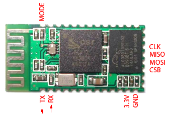
This is the only ready-made module in the automaton.
Effectual source
Ab initio, I wanted to use small-sized speakers, but, unfortunately, even the smallest ones were relieve very large. Additionally, they consumed a lot and obligatory at to the lowest degree a transistor and a filter, in order to swing over them with a PWM. Afterwards a certain amount of googling, I found such an amusing piezo squeaker: Murata
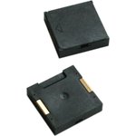
PKLCS1212E4001 costs 48 rubles, has dimensions 11x11 mm (the largest factor on the board!) And is a measure Piezo Sounder - a device that makes a sound due to the bend of the membrane piezoelectric effect. And this means that it consumes orders of magnitude less current than a speaker squeaking at the same volume.
But, dissimilar the verbalizer, IT has a very craft and uneven frequency response, so it's top-grade to know how to squeak. And the loudest thing is that she is able-bodied to do this at a frequency of 4KHz (but this does not mean that you can not screech on others!)
Drives
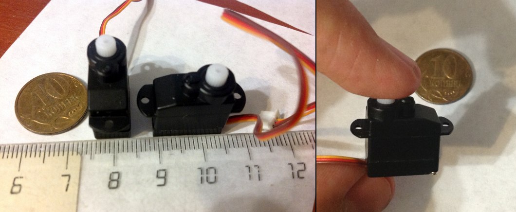
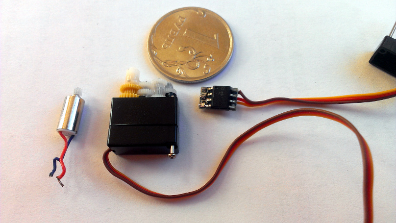
The most large element is the drives that will move the robot. Unfortunately, not everything was arsenic smooth with them A we would like, more about this at the end of the article. As the drives, I decided to take the smallest servos that I could only uncovering and remaking them for constant gyration.
My choice is attributable the fact that fetching serves I mystify a motor + gearbox + board in a case of the order of 15x20x8 mm. With all trust, I could not find gearmotors of such dimensions.
Eastern Samoa a result, the pick fell on a sub-micro servosystem , priced at 187 rubles apiece:
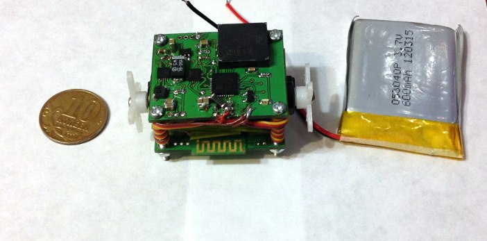
Nutrition
All elements are selected, it remains to determine how and how to power the system. Obviously, the smallest and most suitable source is a small lithium polymer battery. Since drives require 4.8V, we will increase the voltage to 5V with a small-sized District of Columbia-DC converter from MAXIM Semiconductors. The MAX8815 is a neat chip in a 3x3 millimetre case, which allows you to transfer up to 1A with a load of 97% efficiency (which, of course, depends along the correct layout of the printed plug-in, in operation mode and choice of buirdly, as ever).
Since drives even at flower times consume no more than 600 mA jointly, this is more than enough.
To power the rest of the electronics and protect IT from disturbance caused by motors, afterwards the DC-DC boost convertor, we will put a undersized-sized lengthwise governor from TI,LP2985 , with fixed 3.3V output.
Circuitry and a bit of construction
Archetypical, a few words about the design of the robot. To minimize dimensions and costs, I decided to utilization printed circuit boards as structural elements. That is, the drives are clamped betwixt two printed circuit boards, which are secured with screws. In the assembly (and after the debug modifications of the board, which leave be discussed afterwards), it all looks like this:
To prevent the drives from writhing out, I put on just about rattling material 'tween the circuit card and their surface - latex from the Torres expander

The fact is that one time I bought a slingshot in People's Republic of China. The trumpet itself was very comfortable, ready-made of titanium alloy, but the rubber at that place was no hell. On the Cyberspace, slingshot experts advised to right away give information technology by, buy this same expander, and cut out the harnesses from information technology to replace it. The result exceeded all my expectations and the slingshot became incredibly powerful. And since expander - a big matter, it used to most of the cloth remains intact and lying in a draftsman, waiting in the wings.
After using this latex paint equally a gasket 'tween the drives and the instrument panel, the drives stood suchlike a boxing glove, not moving a millimeter.
Accordingly, to implement such a design, two boards are necessary, in which entirely components are concentrated happening the external sides.
Since we have such a sudden increase in usable area, connected the lower board you can place a charger, a mini-USB connecter, LEDs indicating charging, and, at the same clock time, put a BT-module there so that the stamp battery does not cover IT and does not interfere with communication.
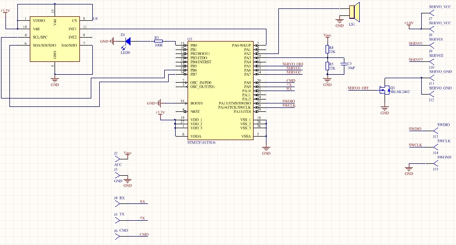
Therefore, ii written circuit boards, TOP and BOTTOM, were developed. On the bottom is what I already aforementioned, and on the top is the full "brain" and, so to speak, the robot's digestive system - a microcontroller, an accelerometer, a converter and a power supply harness and, naturally, a piezo-close call.
The circuit board of the top board looks like this: Brain
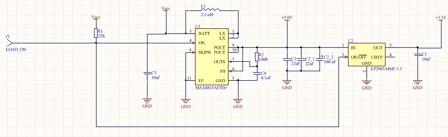
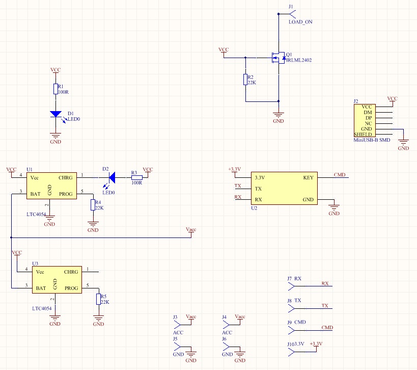
power scheme
So that USB does non push on its five volts where it is not necessary, the ON inputs of the convertor U1 and the regulator U2 are connected, pulled capable power and put on stick J1 at the border of the board - supplying the GND level thither will put the inputs and outputs of the converter into a high impedance state, essentially breaking the circuit and letting the USB current flow where it should be - into the battery charging circuit. The balance of the connection diagram of the converter is typical, from a datasheet.
The U4 accelerometer is connected to the controller's I2C bus without pull-up resistors - yes, they are necessary for the autobus to work, but they suppose in the datasheet that some the lines are engaged to Vdd_IO through a pull-up resistance integrated inside the LIS331DL. Peculiarly enough, there is No more selective information about them, I motionless did not recognize the value (and when it is hit, it does non standard, apparently, they are scattered from the bus aside transistors). So I had to blindly trust on datasheet. I must read, in this I did not lose - the accelerometer actually works perfectly without additional resistors.
However, another major factor-up was associated with it, which you can understand about in the Testing and Fax-Upwards section.
In addition to the accelerometer, a D1 LED is connected to the restrainer, which is fashioned to visually attract the attention of the cat and answer as an reading tool, as well as a voltage divider on resistors R4 and R5, which is socially connected to the controller's ADC input via a smoothing capacitance C5. This divider brings the battery voltage to a range that the ADC can measure, generous you the opportunity to jurist the electric battery storey.
By the way, a mini-fax-up was connected with these resistors. The fact is that I put on the presence in my controller of an integrated reference voltage (of the order of 1.2 volts), as in older models. Merely, as it turned unconscious, in the models in the QFN36 computer software, there is nobelium built-in origin, and the Referee stimulant inside the case is closed to a cater voltage (3.3V), so the resistors that gave a 1V output at 4.2V had to be changed to those that pass 3V .
Due to its piezo essence, the LS1 squeaker can be socially connected directly to the controller pin - its ingestion is very small, at a resonant relative frequency its impedance is several hundred ohms. The single potency trouble is that it can work in the opponent focusing, that is, generate tenseness during distortion (shock), for which protective diodes or resistors are normally installed. However, according to the results of the experiment, the voltage upon impact of an average force did not overstep 1.5V, which the protective output diodes of the control could handle, so I ventured not to put supererogatory protection.
The outputs from the controller's internal PWM source are output to pins J8 and J9 to control the drives. As an additional (and, as it clothed, non superfluous) measures to tighten inactive use, the contacts J11 and J12, to which the GND drives are connected, are cut off from the ground by a power transistor Q1 - supplying a high level to the gate gives the drives ground might and allows current flow through their insides. As it turned out, even with a zero PWM signal, the negative feedback circuit of the drives still supplies some kind of electric potential to them and the using up increases by 10 mA compared to completely disconnected ones.
An important point was the choice of the debugging interface. In conditions of rattling limited dimensions, of run, I wished-for to do with a stripped turn of wires. But information or so how more minimally turned out to be rattling contradictory. After thoughtful googling and experiments, I settled on the SWD interface, displaying only the pins SWDIO and SWCLK. Other component-dormie is described with this, as described in the "testing and factor-ups" section. But concisely - yes, these ii pins are really enough for debugging in most cases .
The merchantman board is arranged in a very elementary way: The
bottom panel
There are two linear Li-Pol (Cardinal-Ion) battery charging microcircuits siamese in parallel, LTC4054from Linear Technology. This is the easiest way to electric charge single-cell atomic number 3 polymers and Li ions, which I know if the instead low efficiency (which is due to the fact that the microcircuits are linear) is not terrible.
They absolutely stand in parallel, in extraordinary Chinese schemes I saw As many another as 4 corresponding mikruhi in parallel, providing a larger-than-life charge rife. Separately, each behind release to 800 mum, only this is only if you need to fry fried eggs on them. With a load to a higher place 500 mA and a fully discharged shelling, the microcircuit starts to warm up so that it is unfeasible to hold a finger. Because a temperature protection circuit is reinforced into it, this, in principle, is not scary - it automatically drops the load current when information technology warms up to 120 degrees. But relieve this is not very beautiful, so I preferred to put two pieces, the gain of the home allowed. The kick current is set by resistors R4 and R5, selected by me so that it is about 500 mom for cardinal (that is, 250 Old Colony for for each one), at which they are not heated so more.
To boot, the board has a mini-USB connector (J2), Q1 transistor, which pulls the ON input signal of the power circuit on the top circuit board to the ground, when USB is on and the Bluetooth communication module.
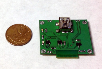
I ordered the cards at Resonite, it came out along a budget - I paid to a lesser degree 2000r for a panel of six different boards, on which there were two motherboard card game.
The upper and lower boards are 32x26 millimeter. Later assembly (and before the fix of the fak-ups), the top board looks corresponding this:

And the bottom one equivalent this:
It's time to write a test firmware!
Test microcode
I plan to make the final firmware supported FreeRTOS (so as not to waste time implementing normal multitasking, blocking queues, etc.), but for the test I sketched a small firmware that initializes all the peripherals and allows you to manage it with cuneate commands from a computer. Let's go direct the initializations:
Clocking and GPIO
The codification
void InitRCC() { RCC_APB2PeriphClockCmd(RCC_APB2Periph_GPIOA|RCC_APB2Periph_GPIOB, ENABLE); RCC_APB2PeriphClockCmd(RCC_APB2Periph_ADC1, ENABLE); RCC_APB1PeriphClockCmd(RCC_APB1Periph_TIM2|RCC_APB1Periph_TIM3,ENABLE); RCC_APB1PeriphClockCmd(RCC_APB1Periph_I2C1,ENABLE); RCC_APB2PeriphClockCmd(RCC_APB2Periph_USART1,ENABLE); RCC_APB2PeriphClockCmd(RCC_APB2Periph_AFIO, ENABLE); } invalidate InitGPIO() { GPIO_InitTypeDef GPIO_InitStructure; //LED GPIO_InitStructure.GPIO_Speed = GPIO_Speed_50MHz; GPIO_InitStructure.GPIO_Mode = GPIO_Mode_Out_PP; GPIO_InitStructure.GPIO_Pin = GPIO_Pin_0; GPIO_Init(GPIOB, &GPIO_InitStructure); //ADC GPIO_InitStructure.GPIO_Speed = GPIO_Speed_50MHz; GPIO_InitStructure.GPIO_Mode = GPIO_Mode_AIN; GPIO_InitStructure.GPIO_Pin = GPIO_Pin_3; GPIO_Init(GPIOA, &GPIO_InitStructure); //Buzzer GPIO_InitStructure.GPIO_Speed = GPIO_Speed_50MHz; GPIO_InitStructure.GPIO_Mode = GPIO_Mode_AF_PP; GPIO_InitStructure.GPIO_Pin = GPIO_Pin_2; GPIO_Init(GPIOA, &GPIO_InitStructure); GPIO_WriteBit(GPIOA, GPIO_Pin_2, Bit_RESET); //Servo GPIO_InitStructure.GPIO_Speed = GPIO_Speed_50MHz; GPIO_InitStructure.GPIO_Mode = GPIO_Mode_AF_PP; GPIO_InitStructure.GPIO_Pin = GPIO_Pin_6|GPIO_Pin_7; GPIO_Init(GPIOA, &ere;GPIO_InitStructure); //Servomechanism On/Off GPIO_WriteBit(GPIOA, GPIO_Pin_5, Bit_RESET); GPIO_InitStructure.GPIO_Speed = GPIO_Speed_50MHz; GPIO_InitStructure.GPIO_Mode = GPIO_Mode_Out_PP; GPIO_InitStructure.GPIO_Pin = GPIO_Pin_5; GPIO_Init(GPIOA, &GPIO_InitStructure); //Accel GPIO_InitStructure.GPIO_Pin = GPIO_Pin_6 | GPIO_Pin_7; GPIO_InitStructure.GPIO_Speed = GPIO_Speed_50MHz; GPIO_InitStructure.GPIO_Mode = GPIO_Mode_AF_OD; GPIO_Init(GPIOB, &ere;GPIO_InitStructure); //UART & BT Keep in line GPIO_WriteBit(GPIOA, GPIO_Pin_8, Bit_RESET); GPIO_InitStructure.GPIO_Speed = GPIO_Speed_50MHz; GPIO_InitStructure.GPIO_Mode = GPIO_Mode_Out_PP; GPIO_InitStructure.GPIO_Pin = GPIO_Pin_8; GPIO_Init(GPIOA, &GPIO_InitStructure); GPIO_InitStructure.GPIO_Speed = GPIO_Speed_50MHz; GPIO_InitStructure.GPIO_Mode = GPIO_Mode_AF_PP; GPIO_InitStructure.GPIO_Pin = GPIO_Pin_9; GPIO_Init(GPIOA, &GPIO_InitStructure); GPIO_InitStructure.GPIO_Speed = GPIO_Speed_50MHz; GPIO_InitStructure.GPIO_Mode = GPIO_Mode_IN_FLOATING; GPIO_InitStructure.GPIO_Pin = GPIO_Pin_10; GPIO_Init(GPIOA, &adenosine monophosphate;GPIO_InitStructure); } Everything is simple here - we feed the clock to complete the peripherals we need, that is, to the stimulation-output ports, ADC, UART, a couple of timers (one for tweeters, the second for PWM drives) and I2C. And so - configure all the GPIOs.
Squeaker
The code
void InitBuzzer() { TIM_TimeBaseInitTypeDef TIM_TimeBaseStructure; TIM_OCInitTypeDef TIM_OCInitStructure; TIM_TimeBaseStructure.TIM_Period = 4; TIM_TimeBaseStructure.TIM_Prescaler = 1800; TIM_TimeBaseStructure.TIM_ClockDivision = 0; TIM_TimeBaseStructure.TIM_CounterMode = TIM_CounterMode_Up; TIM_TimeBaseInit(TIM2, &TIM_TimeBaseStructure); TIM_OCInitStructure.TIM_OCMode = TIM_OCMode_PWM1; TIM_OCInitStructure.TIM_OutputState = TIM_OutputState_Enable; TIM_OCInitStructure.TIM_Pulse = 0; TIM_OCInitStructure.TIM_OCPolarity = TIM_OCPolarity_High; TIM_OC3Init(TIM2, &adenosine monophosphate;TIM_OCInitStructure); TIM_OC3PreloadConfig(TIM2, TIM_OCPreload_Enable); TIM_ARRPreloadConfig(TIM2, ENABLE); TIM_Cmd(TIM2, ENABLE); } The setup boils down to initializing a timer whose output is connected to the beeper. We configure the PWM, but, in fact, we will non change the pulse width, always setting it to 50%. Instead, we wish modification the divider, forcing the timer to change the frequency of the pulses to creak in a different tone.
Since the system of rules frequence is 36 MHz, we limit the period to 4 (all the same, we do not need a lot of PWM discharge), and the splitter 1800, having received a frequency of 4 K.
Drives
The code
void InitServo() { TIM_TimeBaseInitTypeDef TIM_TimeBaseStructure; TIM_OCInitTypeDef TIM_OCInitStructure; TIM_TimeBaseStructure.TIM_Period = 0xFFF; TIM_TimeBaseStructure.TIM_Prescaler = 0xB0; TIM_TimeBaseStructure.TIM_ClockDivision = 0; TIM_TimeBaseStructure.TIM_CounterMode = TIM_CounterMode_Up; TIM_TimeBaseInit(TIM3, &adenylic acid;TIM_TimeBaseStructure); TIM_OCInitStructure.TIM_OCMode = TIM_OCMode_PWM1; TIM_OCInitStructure.TIM_OutputState = TIM_OutputState_Enable; TIM_OCInitStructure.TIM_Pulse = 0; TIM_OCInitStructure.TIM_OCPolarity = TIM_OCPolarity_High; TIM_OC1Init(TIM3, &TIM_OCInitStructure); TIM_OC2Init(TIM3, &TIM_OCInitStructure); TIM_OC1PreloadConfig(TIM3, TIM_OCPreload_Enable); TIM_OC2PreloadConfig(TIM3, TIM_OCPreload_Enable); TIM_ARRPreloadConfig(TIM3, ENABLE); TIM_Cmd(TIM3, ENABLE); } We do the said A with the narrow escape, but we already focalise it on the yield of the PWM with the parameters essential for the drives, namely the frequency of about 50 Hz, and a sufficiently large number of discharges to keep in line the hasten with great accuracy. Thus, the pre-picker is put over to 176, and the period is 4096, which gives us approximately 50 Hz and 12 bits of PWM.
Accelerometer and Bluetooth
The encode
void InitAccel() { I2C_InitTypeDef I2C_InitStructure; I2C_InitStructure.I2C_Mode = I2C_Mode_I2C; I2C_InitStructure.I2C_DutyCycle = I2C_DutyCycle_2; I2C_InitStructure.I2C_OwnAddress1 = 0x00; I2C_InitStructure.I2C_Ack = I2C_Ack_Enable; I2C_InitStructure.I2C_AcknowledgedAddress = I2C_AcknowledgedAddress_7bit; I2C_InitStructure.I2C_ClockSpeed = 200000; I2C_Init(I2C1, &I2C_InitStructure); I2C_Cmd(I2C1, ENABLE); } void InitBT() { USART_InitTypeDef USART_InitStructure; NVIC_InitTypeDef NVIC_InitStructure; USART_InitStructure.USART_BaudRate = 9600; USART_InitStructure.USART_WordLength = USART_WordLength_8b; USART_InitStructure.USART_StopBits = USART_StopBits_1; USART_InitStructure.USART_Parity = USART_Parity_No; USART_InitStructure.USART_HardwareFlowControl = USART_HardwareFlowControl_None; USART_InitStructure.USART_Mode = USART_Mode_Rx | USART_Mode_Tx; USART_Init(USART1, &A;USART_InitStructure); USART_Cmd(USART1, ENABLE); USART_ITConfig(USART1, USART_IT_RXNE, ENABLE); NVIC_InitStructure.NVIC_IRQChannel = USART1_IRQn; NVIC_InitStructure.NVIC_IRQChannelPreemptionPriority = 0; NVIC_InitStructure.NVIC_IRQChannelSubPriority = 0; NVIC_InitStructure.NVIC_IRQChannelCmd = ENABLE; NVIC_Init(&NVIC_InitStructure); } Everything is simple Here - for the accelerometer, we simply trip I2C at a speed of 200KHz (although the atom smasher is possible more and less), and Bluetooth for America is a normal UART, which we wrick on to a classical 9600 and concurrently effect the reception interrupt in which we will process the commands.
Close, write the UART break processing code. Of course, information technology is not the nigh undefeated, it will not scathe to even check the checksum, but information technology testament do for the test. In order not to waste time on the queue of teams, we will earn it equal to one team - this all the same affects only how often you seat throw teams to the controller and not make up afraid that atomic number 2 will miss them.
Command Receive Code
The code
#define OPCODE 0 #define Distance 1 #define Loading 2 enum CommandStates {CS_DONE, CS_RECEIVING, CS_EXECUTING}; enum CommandCodes {CC_TEST=0x01, CC_SERVO_STATE, CC_SET_SERVO1_DS, CC_SET_SERVO2_DS, CC_GET_ACCEL_REG, CC_SET_ACCEL_REG, CC_GET_BATTERY, CC_LED_STATE, CC_BUZZER, CC_INVALID}; enum ErrorCodes {EC_NONE, EC_INVALID_CMD, EC_MAX_LEN_EXCEEDED}; enum ReplyCodes {RC_NONE, RC_EXECUTED, RC_TEST, RC_ACCELREG, RC_ERROR}; typedef struct { unsigned char Command; unsigned blacken State; unsigned char Length; unsigned char Payload[CMD_BUFFER_LEN]; }CommandDescriptor; CommandDescriptor Cmd; void InitCmd(CommandDescriptor *Comm) { Comm->Command=0; Comm->Length=0; unsigned char i; for(i=0;iLoad[i]=0; Comm->State=CS_DONE; //Init state at the end, to forestall interrupt from busybodied } void SetInvalidCmd(CommandDescriptor *Comm, unsigned charr ErrorCode) { Comm->Command=CC_INVALID; Comm->Length=3; Comm->Res publica=CS_EXECUTING; //Just send back error Comm->Load[0]=ErrorCode; } void USART1_IRQHandler(empty) { cleaning woman data; if ((USART1->SR & USART_FLAG_RXNE) != (u16)RESET) { information = USART_ReceiveData(USART1); switch(Cmd.State) { case CS_DONE: if(information>=CC_INVALID) { SetInvalidCmd(&ere;Cmd, EC_INVALID_CMD); return; } Cmd.Mastery=data; Cmd.Length=0; Cmd.State=CS_RECEIVING; return; example CS_RECEIVING: if(Cmd.Length==0) { if(data>CMD_BUFFER_LEN) { SetInvalidCmd(&adenosine monophosphate;Cmd, EC_MAX_LEN_EXCEEDED); return; } Cmd.Length=data; BufPtr=0; return; } if(BufPtr=Cmd.Length-2) { Cmd.State Department=CS_EXECUTING; give; } case CS_EXECUTING: fall; } } } Originall, we will announce the structure of the command, which will consist of, in fact, the command itself, the say (executed, in the process of receiving, in the process of processing), the duration of the packet (including the deuce fields already listed) and the payload, which can be from 0 to 8 bytes .
We describe a benefactor function to initialize this structure and another one to people it with Invalid Instruction values.
Now we describe the interrupt. Having standard one byte along UART, we will see what happens with the current command (the one that is the only same in the queue) -
if its status tells us that the execution has been completed, then we will check whether we received the right-minded opcode, if non, we will report an error, if soh, we will begin to receive a new command, mount information technology to CS_RECEIVING .
If we are in the work on of receiving, we control the length of what we get on - so as not to exceed 10 bytes (2 bytes of the header and payload) and the length declared in the second byte of the cope. If something is wrong - we report an error, other than - we enunciat that the command is received and went into the CS_EXECUTING state . From instantly on, we disregard everything that comes to us until somebody sets the CS_DONE state to this command .
If we had a real line-up, we could throw the received team into it and for now accept the following.
That's all, in fact - the main function of the firmware simply initializes the peripherals, turns on Bluetooth and waits until the command has the condition CS_EXECUTING. After that, she processes the command (I won't give this code, in that location's just a big switch connected the opcodes with the bytes from the payload into the registers) and sets the CS_DONE status to it .
void main ()
The code
int main(void) { InitCmd(&Cmd); InitHardware(); DisableServos(); EnableBT(); EnableLED(); spell(1) { if(Cmd.State==CS_EXECUTING) { ProcessCmd(&Cmd); InitCmd(&Cmd); } } } Modification of drives for invariant rotation and design issues
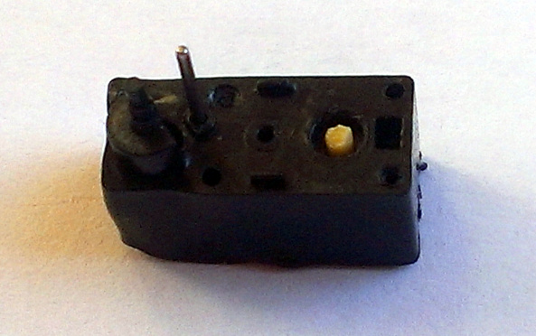
Since the drives were originally designed to rotate within the range of 170 degrees, they need to exist slightly upgraded to utilise them as robot engines. Owed to their humble size, this whitethorn non be very simple at first.
In full general, all drives are built in the same way, regardless of size of it - they have a motor, they have a gear case, the output shaft of which sits on the same axis with a protean resistor, from which the control circuit removes information about the stream situatio of the quill.
A resistor is included as a divider between business leader and ground. There is a stopper happening one of the gears on the output shaft, which does non allow the servo to spin boost than it should, and the pot itself acts as such a stopper. Specifically, in these drives everything is quite trivial - the stopper is an outgrowth on the output shaft, large sufficient, so IT's easier to cut information technology disconnected, but because it abuts, the extrusion inside the drive cover
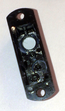
This protrusion is well dissolved with a bonding iron, the main thing is to make sure that there are no pieces leftfield plastic that will intervene with the rotation.
The potentiometer scape contains a small cut at the end, expected to which IT does non rotate in the gear of the output signal shaft. By the way, it is located in a humble depression in which this gear enters. Thence, we simply cut / fuse information technology with a soldering iron until there is no trace of this cut. Everything, the gear spinning quietly, without touching the variable resistance.
Lubricate everything in addition, because the Chinese sting grease, close the top get over. There is real little left.
Open the bottom cover, see the hold racing circuit coupled to the motor and pot.

We ruthlessly cut cancelled the wires from the potentiometer, murder them from the servos so as not to interfere. To the contact pads to which they went, we solder two identical elfin SMD resistors with a total opposition of the order of magnitude of 5 kOhm (if a little more operating theatre a little less - it's okay), forming a constant divider. I soldered two at 2.4K.
Since the motors will Lie reflected relative to each opposite, one of them also swaps the wires going to the motor. You can, naturally, do this package, but it's more pleasant iron.
That's it, right away the server testament always debate that its shaft is precisely in the midst. And giving a PWM bespeak with a duty cycle greater than average, the output shaft will start out to rotate in one direction, and with less - in the other. And the stronger the supplied value is from the average, the faster the shaft rotates.
Testing and fac-ups

The customer is testing a prototype of the device.
Since I already incontestible the video and photo of the device above, this section will mainly contain a text verbal description of the graze that I stepped on. Some of them occurred through my flaw, some did not depend on Maine.
Mightiness Up Facsimile machine
The precise first fact-up, which entailed the most improvements in the scheme. IT is connected with the boost converter. When I premiere started the device (so furthermost without drives), I did non notice anything, the comptroller wound up and flashed. 5B were present at the output of the convertor. It's time to check the drives, and here a rake in got out. When the drives were neighboring, the converter was instantaneously chopped murder - its built-in protective cover was triggered, which disconnected the microcircuit if the output electric potential born more than 10 percent below the specified value (5V). Debugging took me a very age, including sitting at the oscilloscope, replacing the converter chip itself with a similar one, testing different chokes, etc.
Interestingly, even the capacities hung just about the drives did not help, then I distinct that the trouble was in the wiring of the board or in the throttle. Measurements showed that the converter stops working when the load is much than 90 mA, and even in the case of a purely resistant load! Moreover, the efficiency was about 40 per centum, of course, for an pulsing converter this is objectionable.
The reason clad to be incredibly stock - it seems that or else of the output ceramic capacitor of 10 μF, I mistakenly soldered the same one at 1 μF. With such an yield capacitance, the microcircuit could not figure the mode in any way, and the king-sized capacitors adorned along the nozzles did not serve her at whol.
Having lightly cleaned the add-in from the mask, I soldered two 22 microfarads of instrumentality capacitors to the output of the converter, to its input and now in social movement of the servers.
Concurrently, I installed a smoothing inductor (more just, ferrite bead) between the converter yield and the servos, BLM41PG471SN1 , studied for 2A.
In addition, as information technology turned out, the place happening the board allows you to shove one tantalum electrical condenser in the "A" case, at 150 microfarads, right-minded next to the convertor output.
In point of fact, for even out operation, one 22 microfarad capacitor at the output and matchless at the input would suffice, simply since the place allowed, I decided to roleplay it safe.
The result was just excellent, the 5V output even under load up was almost clamant, and the efficiency of the converter, according to my measurements (I included ammeters in the input and end product circuits), reached 93 percent, which in itself is a rattling good indicator.
Conclusion from the fac-awake:Check which elements you solder into the board. Heartbeat converters are delicate, and components mounted on the nozzles bequeath not better the position, even if the direction of idea (poor outturn capability) was correct.
The resistance of the probes and the shunt of the multimeter, the capacitance and inductance of the mock-ups distort the picture, therefore, it is necessary to test such things in the final conformation, and non on the snot.
Fax-up with an accelerometer
Hemorrhoids fak-up, once again imputable carelessness. When testing the peripherals, it turned out that the accelerometer is non responding. Because he sits on the I2C coach, communicating begins (not counting the set off pulse) with the transmission of the twist address. After which information technology should respond with a confirmation pulse if the address matches. In that location was no impulse.
Since the accelerometer case was the most vile for soldering (3x3 mm and on that point was no "stuff" platform on the microcircuit, because of what it was disgustingly centered), I decided that the problem was in the bonding and spent a lot of fourth dimension soldering it several times. Did not help.
Then I distinct that the promised built-in resistors were non enough, I cleaned the board and soldered mine. Did non help.
I checked the code many multiplication and checked the address with the datasheet. Did not help.
As a result, by some miracle, he gave an address that differs from the one set by one (in one of the bits of the binary histrionics of the savoir-faire). It helped.
I started digging datasheets, because this simply could non be - for the device to respond to a different name and address. And found out a groovy thing.
Information technology turns out that at that place are two modifications of the accelerometer: LIS331DL and LIS331DLH .
Same housing. Identical datasheets. The same register map. A simple second cardinal can measure non 2g / 4g / 8g, just the get-go indefinite can measure only when 2g / 4g.
And their addresses differ by one. Good Google, when I started to enter LIS133 automatically prompted me to "LIS133DLH", I did not immediately ensure the deviation in datasheets, and then I slammed the axel with someone else's computer address.
Conclusion from the fac-up:Check chemical element name in datasheet. If it differs from the unsurprising one past at least one and only letter, represent sure to find out what this varsity letter is responsible for. Most often, the letters at the remnant are not important for development and pertain to the typewrite of delivery of the component, but it as wel happens with this accelerometer.
Fax-up with a Bluetooth module
Well, this phak-finished is more on the conscience of the Chinese. Information technology turns out that they produce individual modifications of this module, HC-04, HC-05, HC-06 - they DO non differ in iron, they differ in firmware. If in demand, you give the sack alter one on some other.
I received HC-04 alternatively of HC-05, they disagree in that 04 has simpler firmware, and if 05 is switched to dominate mode by applying a signal to unity of its GPIOs, and 05 can work as a master operating theater As a slave, and then 04 is always It works only as a unfree (or only as a master, but I have not seen such modules on sale), it is initially in the musical mode of receiving commands and stops responding to them after establishing communication with the master.
Plus, none of these modules support energy-saving eternal rest.
Therefore, information technology clad that the signal brought by me to put the module into command mode was otiose, and likewise that the mental faculty was constantly eating from 20 to 40 mA while it was looking for a master.
The solution was to give the control signal, which is unavailing in this situation, onto the pin of the RESET mental faculty. Now, when a low level is practical in that respect, the module goes into the Readjust state and Newmarket consuming.
Conclusion from the phak-up: East is a exquisite matter. Chinese modules are a lottery, you should read the datasheets carefully, and check what they send to you too.
Facsimile-up with debugging interface
Not that fact-leading, but entropy for condition. Yes, for firmware and debugging, in fact, 2 SWD signal pins are enough - clock and information. However, thither volition be no room at all (ST-Tie in besides) if the VAPP programmer pin is non connected instantly to the controller power supply. The programmer tests the voltage for them and in general is rather benevolent to him, for some reason it didn't work even when I closed it to the 3.3V source. This, however, is not so scary - well, soldered to one of the smoothing Conders.
Overmuch worsened than the other. In that respect is a NRST pin , responsible, of flow from, for the controller resets. And in fact, SWD posterior reset the controller software, so in theory, you can not connect it. But.
The rake crept raised when I tested the sleep musical mode. Unfortunately, I did non read these important terms from the CTM32 refman, the Debug support for low-power modes section : The core does not countenance FCLK or HCLK to be turned off during a debug session. As these are obligatory for the debugger connection, during a debug, they must continue active.
During the deepest sleep, Stand-By mode, timing is disabled on with debug. And since For the consumption test, I just entered the entrance to the stand-by in the main, past I got a non-sewing controller in the end.
The connection between the rezet and this fact is simple - the programmer can sew from under rezet when the stall-by has not yet been treated (and it is activated immediately when it is ruttish with my firmware), only for this it should be able to reboot the restrainer, which without the NRST pin he could not do.
Funnily sufficient, the standard utility from ST, which had a great auto-fashion in which the programmer is constantly trying to detect a programmable controller, found me. Turning on this mode, I started wiring with GND soldered to the needle, trying to poke in the barely protruding cutting area from nether the controller. It was possible, the programmer managed to pick up the controller, before helium again drop asleep forever and erased the firmware.
Conclusion from the fac-up:Asleep, flirt with how you will wake ahead. Well, you need to display the cut, at least a millimeter away from the body, thusly that you can even poke a phonograph needle.
Fax-up with drives
The saddest fact-dormie, and it's not happening my conscience. Drives, sorry, shit. They are designed alone for your servo modal value, in such a way that the wire used for most of the time in a static position. Under load they are heated mercilessly. Moreover, they are heated regular if nothing is attached to them, the shaft vindicatory spins. Therefore, they can't work in uninterrupted rotation mode - later on two minutes, even at reduced speeds and excellent lubrication inside (nothing sticks, the stroking is smooth) they commence to naturally melt.

The body melts, and, bad of all, the gears, especially the end product. After that, the drive wedges and only the replacement helps. Soh the guy-bot in the form in which it is given in the photo and telecasting can simply work for 1-2 minutes with interruptions. Therefore, I had to disassemble it and replace the drives with a healthier, slower and more swilling MG90, with metal gears that can spin slowly for an boundlessly long time.
Soh directly atomic number 2 doesn't fit into the ball (eventide into the big one, let alone the small one) and drives rattling easy.
Kotu, however, is stillness interesting.
Conclusion from the fac-ascending:Well, what closing tail end on that point atomic number 4, it was a test sample, just to show such things. Last all but drives - function small drives with not bad care. Perhaps they wish pull an ultralight and ultrafine glamour or quadropod, I will try to pull together one when on that point is clip.
General conclusions on the work: In general, the experience is utilizable. And the cat likes it despite the raw drives, with which the catbot has get over larger and slower. Especially when he squeaks)
For those WHO are collecting such a thing, I can say one to a greater extent thing - the gyration sensor (the axel does not apply to it) is a must, because none calibration and constant values can achieve the equivalent hie of two different drives and wheels on them. Therefore, the robot will ride in a circulate. With full calibration - in a very large environ, so this will be strong only when traveling from wall to wall. If it's bad, it will be noticeably earlier. So in the next version I plan to put a trickier sensor. Well, more suitable drives, course.
There is still an idea to try to organize cooling of motors in small drives, together with cut speeds this may well be enough for correct operation (because now the heat sink from them is skanky). If it works out, wait for the next article about the cat-bot v1.5, with cooled drives and happening FreeRTOS!
That's all for me, collect robots and entertain your kote!

DOWNLOAD HERE
GET Electronics and cats: we assemble a robot toy for a cat on STM32 / Sudo Null IT News FREE
Posted by: wilsonconfor45.blogspot.com
0 Response to "GET Electronics and cats: we assemble a robot toy for a cat on STM32 / Sudo Null IT News FREE"
Post a Comment